This is an old revision of the document!
Table of Contents
Cartridge port
50 pin connector with spacing of 2.54mm. For example this works: https://www.digikey.com/product-detail/en/te-connectivity-amp-connectors/5530841-5/5530841-5-ND/2259225
One pair of pins is missing, making a hole that prevents inserting cartridges in the wrong way.
V.Smile cartridges
Pinout traced from development cart picture: https://media.discordapp.net/attachments/750094909947772964/758513072087629884/vsmile-pinout.png?width=1011&height=684
Development cartridges from V.Tech used NOR flash memory: SST 39VF6401B (4Mx16 flash memory). The write pin is exposed on the cartridge port, so in theory it's possible to reflash it directly from the console?
Production cartridges use a “blob” and it's unknown what exactly is under it. Probably mask ROM.
| Pin N | 1 | 2 | 3 | 4 | 5 | 6 | 7 | 8 | 9 | 10 | 11 | 12 | 13 | 14 | 15 | 16 | 17 | 18 | 19 | 20 | 21 | 22 | 23 | 24 | 25 |
|---|---|---|---|---|---|---|---|---|---|---|---|---|---|---|---|---|---|---|---|---|---|---|---|---|---|
| Front | /WE | /OE | GND | D3 | D4 | D5 | D6 | D11 | D12 | D13 | D15 | A0 | A1 | A3 | x | A5 | A7 | A18 | A9 | A11 | A13 | A15 | A20 | GND | Card detect |
| Back | VDD | RAM CSB | Sense | ROM CSB2 | D2 | D1 | D0 | D7 | D10 | D9 | D8 | D14 | A16 | A2 | x | A4 | A6 | A17 | A8 | A10 | A12 | A14 | A19 | A21 | ROM CSB1 |
Note: the “back” side is the one with the label. Chips inside the cartridge are on the side with no label.
- Sense is connected to VDD to indicate that a cart is inserted. It is connected to the RESET pin, so inserting a cartridge will power the console off.
- Card detect is connected to VDD to indicate that a cart with ROM is inserted (?) maybe it allows booting from cartridge instead of internal ROM (tbc)
- ROM CSB1, ROM CSB2 and RAM CSB allow to select which bank of the cartridge is accessed. Typically cartridges use only ROM CSB1, but larger cartridges (example: alphabet adventure) need two ROM banks.
RAM CSB is used for the battery backed-up SRAM cartridges
To be confirmed:
- What is the max capacity? Since we have 3 bits (RAM_CSB, ROM_CSB1 and ROM_CSB2), can we fully control them individually and address 7 different spaces of 22bit each?
- What is RAM_CSB? It is not connected on the only cart known to use SRAM.
Battery backup cartridge
At least the “Studio de Dessin” cartridge (the one for the graphic tablet) has backup SRAM
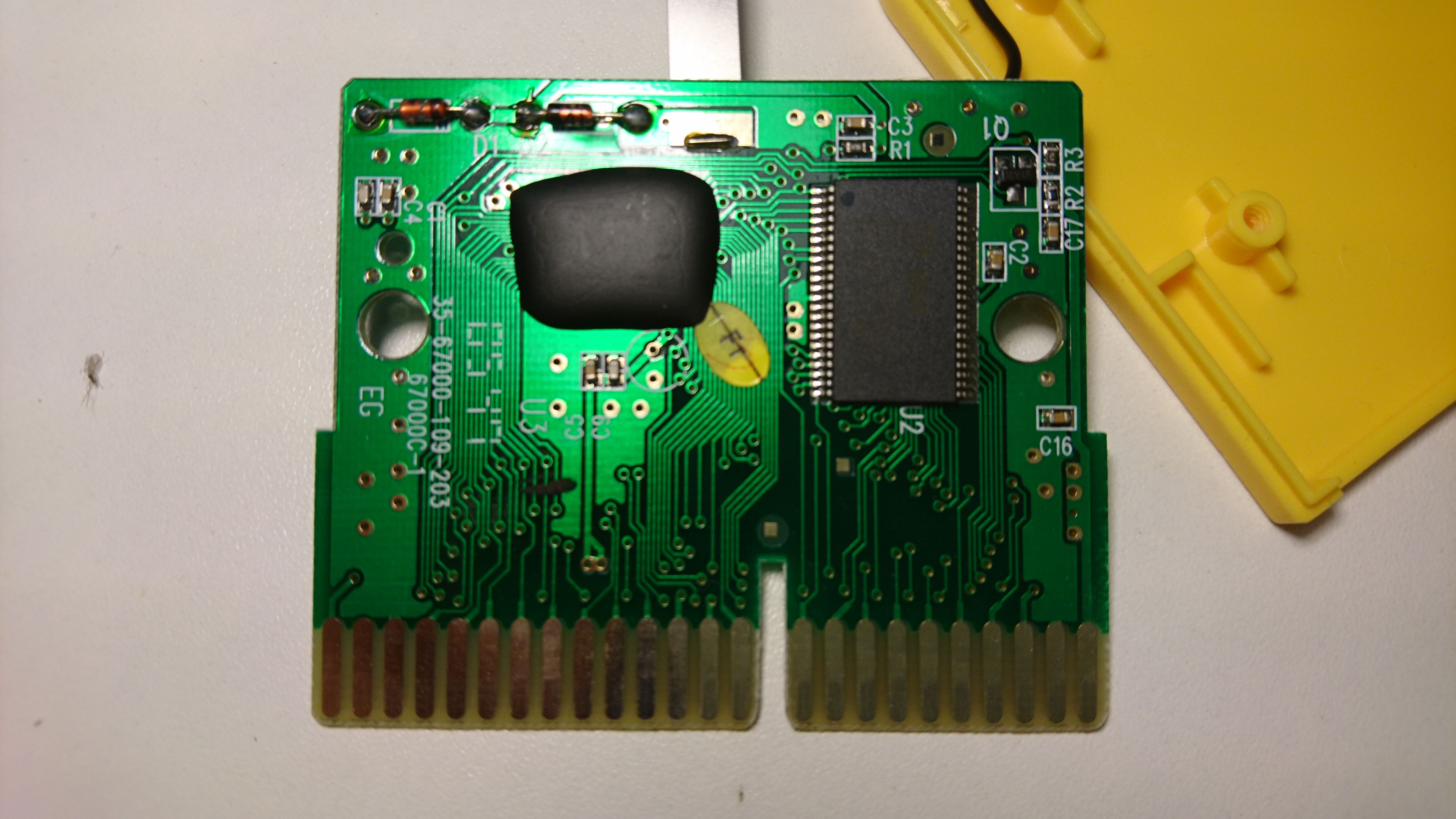
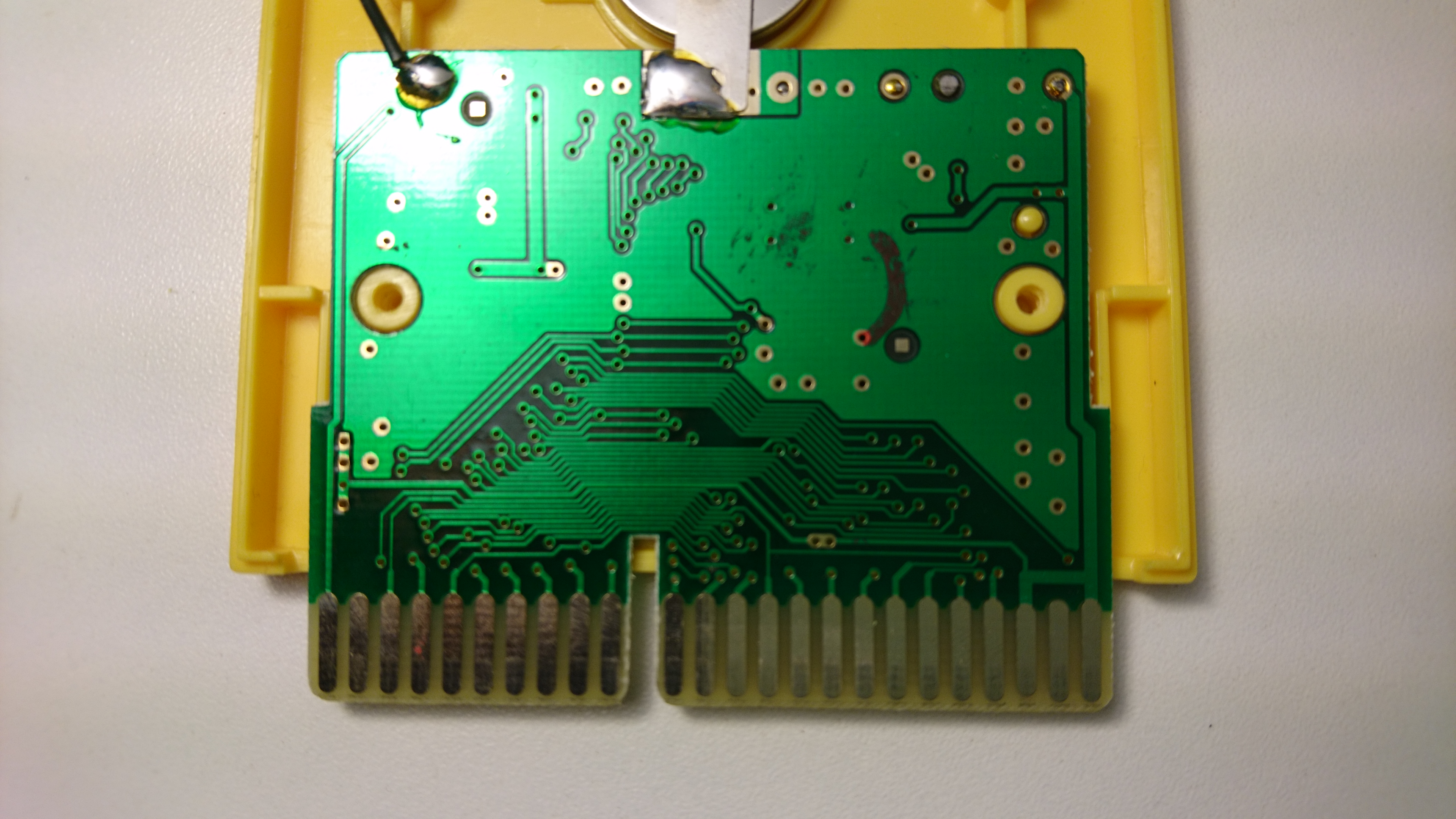
The blob is flash (as usual) and the chip on the right is RAM: BSI - BS616LV2016ECG70 - S31688EB04308B1 - E05162 - Taiwan
 The pin labelled RAM_CSB in the pinout above is in fact not used by this cartridge (but ROM_CSB2 is)
Nitro Vision / Genius TV progress cartridges
These contain no ROM, and only short some pins together.
Inserting these in the V.Smile results in nothing special (the boot animation loops as if there was no cartridge). However the SENSE pin is there, so they still power the console off if connected while it is on.
| Cartridge name | Number (marked on PCB) | Shorted pins |
|---|---|---|
| Français et Anglais (orange) | 1 - 35-68700-017-202-707426-1 | SENSE is connected to VDD |
| Sciences et Nature (white) | 2 - 35-68700-018-202-707427-1 | SENSE and RAM_CSB are connected to VDD |
| Découvre le monde (blue) | 3 - 35-68700-019-202-707428-1 | SENSE and ROM_CSB2 are connected to VDD |
| Maths et Logique (green) | 4 - 35-68700-020-202-707429-1 | SENSE, RAM_CSB and ROM_CSB2 are connected to VDD |
So, in this case:
- Sense indicate that a cartridge is inserted
- RAM_CSB and ROM_CSB2 allow to identify which cartridge it is
Controller port
6 pin mini DIN (like PS/2 keyboards and mouse). It is a serial port at 4800 baud, 8N1.
Pinout (using the standard numbering for mini-DIN connectors) :
- VCC
- CTS (from V.Smile)
- Tx (from V.Smile)
- GND
- Rx (from controller)
- RTS (from controller)
Flow control
When the console sends a byte, first CTS goes high, then the console sends the bits on the Tx line. When done, CTS goes low again.
When the controller sends a byte, RTS goes low first, then it waits for CTS to be up. Then RTS goes up and sends its byte. Finally CTS goes low again.
If there are multiple bytes to send, RTS remains down until the start of the last byte.
Messages from the controller
When idle (no buttons touched), the console sends a byte every 20ms, it seems to be partially random. I've seen E6, D6, or 96.
Every second the controller sends 55 if nothing else is happening.
| Common to joystick, dance mat and keyboard | ||
|---|---|---|
| Button | Press | Release |
| OK | A1 | A0 |
| Quit | A2 | A0 |
| Help | A3 | A0 |
| ABC | A4 | A0 |
| Idle (nothing) | 55 | |
Joystick
The joystick has 5 levels of precision in each direction. For example, C3 is “slightly up”, C7 is “all the way up”.
The 4 color buttons are allocated one bit each in the 9x range so it's possible to manage multiple of them being pressed at once.
The other buttons are Ax with x just being the button number, so it's not possible to handle multiple of them being pressed at the same time.
| Joystick | ||
|---|---|---|
| Button | Press | Release |
| Green | 91 | 90 |
| Blue | 92 | 90 |
| Yellow | 94 | 90 |
| Red | 98 | 90 |
| Up | C0 83 to C0 87 | C0 80 |
| Down | C0 8B to C0 8F | C0 80 |
| Left | CB 80 to CF 80 | C0 80 |
| Right | C3 80 to C7 80 | C0 80 |
Dance mat
Every press sends at least a “joystick position” 2-byte pair, and possibly an extra byte for the button itself (some buttons report as joystick moves, other as separate buttons). The mapping is not at all compatible with the joystick and seems a bit random. Note that for example 8B and 8D are different buttons, where on the joystick it would be different positions in the same direction.
| Dance mat | ||
|---|---|---|
| Button | Press | Release |
| 1 / Red | C0 8B | C0 80 |
| 2 / Up | 92 C0 80 | 90 C0 80 |
| 3 / Yellow | CB 80 | C0 80 |
| 4 / Left | C0 8D | C0 80 |
| 5 / Middle | 91 C0 80 | 90 C0 80 |
| 6 / Right | CD 80 | C0 80 |
| 7 / Blue | A4 C0 80 | A0 C0 80 |
| 8 / Down | 94 C0 80 | 90 C0 80 |
| 9 / Green | 98 C0 80 | 90 C0 80 |
Smart Keyboard (Clavier Tip Tap)
(sorry, I have the French/azerty version so key labels may not match up. The table is in row/column order)
| Row 1 (top) | Row 2 | Row 3 | Row 4 | Row 5 | |||||
|---|---|---|---|---|---|---|---|---|---|
| Key | Code | Key | Code | Key | Code | Key | Code | Key | Code |
| Esc | A2 | Dactylo | 22 | Caps | 1A | Shift | A9/AA | Player 1 | 04 |
| 1 | 33 | A | 23 | W | 13 | Help | A3 | ||
| 2 | 34 | Z | 24 | Q | 1B | X | 14 | Symbol | 2C |
| 3 | 35 | E | 25 | S | 1C | C | 15 | Space | 05 |
| 4 | 37 | R | 27 | D | 1D | V | 17 | Player 2 | 0E |
| 5 | 36 | T | 26 | F | 1F | B | 16 | Left | 06 |
| 6 | 30 | Y | 20 | G | 1E | N | 08 | Down | 0F |
| 7 | 31 | U | 21 | H | 18 | , | 11 | Right | 0D |
| 8 | 3E | I | 3A | J | 19 | ; | 0C | ||
| 9 | 3F | O | 3B | K | 0A | : | 2F | ||
| 0 | 38 | P | 3C | L | 0B | Up | 12 | ||
| º | 29 | ¨ | 2A | M | 01 | ||||
| Backspace | 39 | Erase | 3D | Enter | A1 | ||||
- Escape is mapped to Quit and works the same
- Help is mapped to Help and works the same
- Enter is mapped to OK and works the same
- Shift sends A9 on press and AA on release
- Other keys send their code on press, and code | C0 on release (so no code will be in the 90-AF range for either press or release to not conflict with the special buttons)
The joystick at the bottom of the keyboard is similar to the normal Joystick but uses different values (to avoid clashing with the keyboard release keycode range). There does not seem to be different values possible, it's all on or all off.
- Left: 7F 80
- Right: 77 80
- Down: 70 8F
- Up: 70 87
Commands from the console
61, 62, 64 and 68 are sent in reply to color buttons presses. I suspect this controls the lights in the buttons. 60 is sent to turn the light off.
These are repeated every 20ms. After the controller sends 55 (idle), the V.Smile also returns to its idle reply (E6 for example) every 20ms.
