Table of Contents
Currently documented at https://github.com/vsmile-dev/vsmile-hardware-docs/blob/master/ppu.md
The PPU is an earlier version of the one used in GeneralPlus current GPL951 series of chips. That newer series has a publicly available code sample including register descriptions and other info.
From https://www.generalplus.com/3LVlangLN5SVprot_noSNproduct : AppNote showing how to use the PPU
The application note contains a PDF showing the register layout (Document/GPL951xx PPU driver_user.pdf) and C files with a complete library to use it (PPU/ directory). However, it uses some of the new features in later generations and is not compatible with the V.Smile.
The PPU provides two background layers (which can use either tiled or bitmap modes), on top of which sprites can also be displayed.
Basic info about tiles
The PPU works with tiles. The idea of tiles is to have small square or rectangular images (8×8 up to 64×64 pixels) and use them to compose a larger image. The advantage of this is that some tiles can be reused in multiple places, which provides a simple compression method. Also, a tile can be quickly replaced by another, without copying a lot of bytes around in RAM, to animate things.
There are two layers of tiles that can be put on top of each other. Each layer can have a different color depth, color palette, tile size, blend setting, layer depth, and also vertical and horizontal mirroring. They can also be scrolled vertically and horizontally.
Each layer has a tile map. This is a chunk of memory that is filled with index of tiles, going left to right and top to bottom. The index is multiplied by the tile size (depending on the width, height, and bits per pixel) and added to the segment pointer of that layer to find the address of the bitmap data for that tile. Then, that bitmap is displayed. The index of 0 has a special meaning as it will draw an entirely transparent tile.
In addition, each layer supports an optional attribute map mode that allows setting the blend setting, palette and mirroring of each tile individually. The attribute map is a memory chunk organized in the same manner as the tile map, except that each word stores data for two tiles instead of one. Each layer also supports an optional scrolling mode where in addition to the normal layer scroll, each line has additional individual horizontal scrolls. The array controlling the scroll of each line is shared between the two layers.
It's also possible to use a bitmap mode, but this needs a lot of memory. Since the V.Smile doesn't have much RAM, typically, only fixed bitmaps read directly from ROM will be used in this case.
Register map
| Address | Contents |
|---|---|
| 2810-2815 | Layer 1 |
| 2816-281B | Layer 2 |
| 281C | Vertical scale (8 bits) |
| 281D | Vertical movement |
| 2820 | Layer 1 segment pointer |
| 2821 | Layer 2 segment pointer |
| 2822 | Sprite segment pointer |
| 282A | Blending level (2 bits) |
| 2830 | Fade level (8 bits) |
| 2836 | Vertical compare for IRQ (9 bits) |
| 2837 | Horizontal compare for IRQ (9 bits) |
| 283C | Hue and Saturation adjust (8 bits each) |
| 283D | LFP (bit 2), Interlace (bit 0) |
| 283E | Lightpen vertical position (9 bits) |
| 283F | Lightpen horizontal position (9 bits) |
| 2842 | Sprites enable |
| 2854 | LCD control (bits 4 and 5: framerate, bit 3: CkvSel, bit 2, resolution, bits 1 and 0: color mode) |
| 2862 | IRQ control (bit 2: DMA, bit 1: VDO, bit 0: blanking) |
| 2863 | IRQ status (same layout) |
| 2870 | DMA source address |
| 2871 | DMA target address (9 bits) |
| 2872 | DMA transfer length (9 bits) |
| 2900-29FF | Text horizontal control |
| 2A00-2AFF | Horizontal scale |
| 2B00-2BFF | Color palette (15 bit RGB and bit15 indicates transparent colors) |
| 2C00-2C03 | Sprite 0 |
| 2C04-2C07 | Sprite 1 |
| … | … |
| 2FFC-2FFF | Sprite 255 |
Layer 1 and 2 registers
| Address | Function |
|---|---|
| 2810/2816 | X position |
| 2811/2817 | Y position |
| 2812/2818 | Attributes |
| 2813/2819 | Control |
| 2814/281A | Tilemap address |
| 2815/281B | Attribute map address |
| 2820/2821 | Tile data segment |
Each layer can be positioned at any X and Y coordinate on screen. They have a fixed size of 512×256 pixels, with the number of tiles depending on the chosen tile size.
The following global attributes are available:
- Bit depth (bits 0 and 1)
- 00 - 2 bits per pixel
- 01 - 4 bits per pixel
- 10 - 6 bits per pixel
- 11 - 8 bits per pixel
- Bit 2: Mirror the tiles horizontally
- Bit 3: Mirror the tiles vertically
- Bits 4-5: Width of tiles
- 00 - 8 pixels
- 01 - 16 pixels
- 10 - 32 pixels
- 11 - 64 pixels
- Bits 6-7: Height of tiles
- Same format as width register
- Bits 8-11: Palette bank to use
- Bits 12-13: Layer depth (wether it is under or over sprites and the other layer)
- 00 - bottom layer
- 01 - second-bottom layer
- 10 - second-top layer
- 11 - top layer
- Bits 14-15: unused (in later PPU generations it sets the layer size)
The control register can do the following:
- Bit 0: Use bitmap mode instead of tile mode
- Bit 1: If set, the attribute register is used. If clear, the attributes are fetched from the attribute map in RAM (like the tilemap) and can be different for each tile.
- Bit 2: Use wallpaper effect (only first character/line attribute is effective)
- Bit 3: Enable the layer
- Bit 4: Enable horizontal movement
- Bit 5: Enable horizontal compression
- Bit 6: Enable vertical compression
- Bit 7: Use direct colors instead of palette (each 16-bit word is a 15-bit RGB value)
- Bit 8: Enable blending
When the attribute map mode is used, each word stores attributes for one tile in each byte in the following format:
- Bits 0-3: Palette bank to use
- Bit 4: Mirror the tiles horizontally
- Bit 5: Mirror the tiles vertically
- Bit 6: Enable blending
The tile map and attribute map addresses are 13-bit values, so they have to be in RAM.
The tile graphics themselves, however, are usually stored in flash. The data segment register defines the segment where to find tiles. To compute where the data for a tile is, use: data segment * 0x40 + tile id * tile size in words
Sprite registers
| 0 | Sprite char select |
| 1 | Sprite X position |
| 2 | Sprite Y position |
| 3 | Sprite attributes |
Each sprite has an X and Y position and an attribute register that works the same as for the layers. The attribute register has an extra bit (bit 14) to enable blending. The blending level is global for all sprites and there are only 4 possible values. The sprite is disabled by setting the char select to 0.
The sprite position refers to the center of the sprite (rather than top left corner) and contains signed values with pixel position x=160,y=128 as the origin of the coordinate system and positive Y going upwards.
Unlike for layers, there is no tile and attribute map: a sprite is made of one single tile, with the character ID is stored directly in the corresponding register for the sprite.
The sprite attribute register format is the same as the one for tile layers, with the exception of bit 14 being assigned to blend enable.
Colors and palettes
The PPU supports 15-bit color, with colors stored in the following format:
- Bits 0-4: Blue value
- Bits 5-9: Green value
- Bits 10-14: Red value
- Bit 15: Set if transparent
In the 16-bit color mode, the value of each pixel in the segment memory directly stores a color, otherwise the value refers to a palette index. The palette memory is mapped to 0x2B00-0x2BFF and stores 256 different colors in the format mentioned above. This memory can be split into multiple palette banks which can then chosen by a 4-bit value stored for each sprite, tile layer or individual tile (if the attribute map mode is enabled).
The chosen color from the palette memory is determined by the chosen color depth and palette of each tile/sprite and value of each pixel as follows:
| Color depth | Chosen color memory index |
|---|---|
| 2-bit | Palette * 16 + Index |
| 4-bit | Palette * 16 + Index |
| 6-bit | (Palette & ~3) * 64 + Index |
| 8-bit | Index |
Special effects
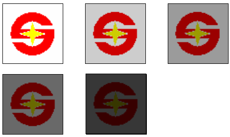
The fade level allows to do a “fade to black” effect easily. Higher values result in a darker display. It affects the whole display (both tile layers and the sprites).
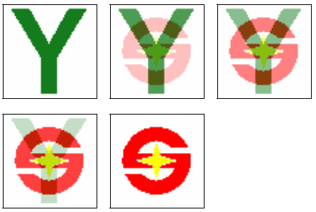
The blend effect allows for partially transparent tiles and sprites. There is a single blending level shared by all blended objects, but each object can be either blended or fully opaque. When the tile layer is in attribute map mode, the blend effect can be set for each individual tile, otherwise the same blending will be applied to the entire layer.
Interrupts
The PPU interrupt can trigger (if enabled in the IRQ register):
- When the DMA completes a transfer
- At the start of vertical blanking (every frame)
- When reaching a specific vertical and horizontal pixel position (registers 2836 and 2837)
